
Top Motor Braking Resistor Types for Industrial Buyers
Choosing a Motor Braking Resistor is not just a matter of matching a part to a motor’s nameplate. During deceleration, a drive may send excess energy to the resistor, where it becomes heat. The resistor must handle that heat repeatedly and safely. A poor match can cause overheating, nuisance trips, or slower stopping than the process requires. Details matter.
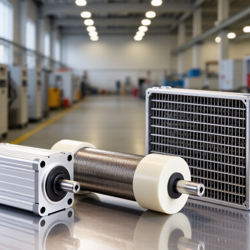
Industrial buyers commonly compare wirewound, aluminum-housed, and grid-style designs. Each serves different operating conditions. Compact aluminum-housed units can suit limited spaces, while grid resistors are often considered for heavier braking duties and demanding environments. Wirewound models offer another option where the required resistance and power rating align. These are not automatic rules. Duty cycle, braking frequency, airflow, enclosure, and mounting location can change the decision. A dusty control cabinet, for example, creates different thermal concerns from an open machine frame.
This guide introduces the main resistor types and the specifications buyers should verify before selecting one. Start with the drive manufacturer’s recommended resistance range, then check peak power, average power, and permitted braking time. Compare those figures with the machine’s actual stopping pattern. A datasheet is useful, but it cannot replace a realistic duty-cycle assessment. That part is sometimes overlooked. When operating conditions are uncertain, confirm assumptions with the drive or resistor supplier and a qualified engineer. The best choice is not always the largest unit; it is the one that manages heat reliably within the real application.
How Motor Braking Resistors Control Industrial Drives
A motor braking resistor gives a variable-frequency drive a place to send excess energy during deceleration. When a motor slows a heavy load, it can briefly act as a generator. That energy raises the drive’s DC-bus voltage. A brake chopper detects the rise and directs current through the resistor, where electrical energy becomes heat. This is controlled energy dissipation, not a mechanical holding brake. Heat matters.
In practice, resistor selection depends on resistance, pulse energy, braking frequency, and the drive’s limits. A conveyor stopping every few seconds creates a different thermal load from a fan that stops occasionally. Wire-wound and grid-style resistors handle heat differently, but neither is automatically the right choice. Check the drive manual and calculate the load’s stopping energy; do not size by motor power alone. A neat calculation can still miss real operating patterns.
Mounting matters too. Keep the resistor clear of cables and heat-sensitive surfaces, and provide the ventilation specified for its enclosure. After commissioning, measure resistor temperature during repeated stops and watch for unexpected drive overvoltage faults. Not perfect? Field measurements can reveal assumptions that the spreadsheet missed.
Major Types of Motor Braking Resistors
Motor braking resistors are commonly grouped by construction and duty, though these categories can overlap. Wirewound resistors use resistance wire around a core and suit many compact drives with moderate braking demands. Aluminum-housed models package the element in a ribbed case, which helps transfer heat to surrounding air. Check mounting clearance; a tight cabinet can trap heat.
For higher pulse loads, grid resistors use metal strips or grids with open spaces around them. This structure supports airflow and can handle repeated braking cycles when correctly sized. Ceramic-encased wirewound types offer a protective enclosure, but their heat still needs a safe path away from nearby components. Hot means hot.
In practice, selection depends on the drive’s braking chopper, pulse energy, cycle frequency, and installation environment. A resistor that handles one short stop may overheat during frequent stops. Compare the rated resistance, peak power, and duty cycle with the drive documentation, then confirm ventilation and temperature limits. Catalog labels are not always consistent, so inspect the construction details rather than relying on the type name alone. The enclosure matters too. A good specification can still fail if dust blocks airflow or cables sit too close.
Major Types of Motor Braking Resistors
The index is a qualitative comparison of typical suitability for high-energy braking—not a standardized rating or a substitute for checking a resistor’s pulse-energy, duty-cycle, and thermal specifications. Actual performance depends on the design and operating conditions.
Resistor Materials, Enclosures, and Cooling Designs
Motor braking resistors turn excess regenerative energy into heat, so material choice matters as much as the rated resistance. Wirewound elements suit many compact assemblies, while stainless-steel grids tolerate demanding industrial duty and allow airflow around the element. Alloy selection affects temperature capability and resistance stability. Heat matters.
Enclosures should match the actual installation, not just the catalog description. A dusty packaging line may need protection against particles, while a washdown area needs a suitable sealed design and careful cable entry. More sealing can restrict heat release, however. Check enclosure temperature limits alongside the resistor’s duty cycle and peak braking energy. A tidy specification sheet can still miss a hot spot near a wall or cable tray.
Cooling design depends on operating frequency, ambient temperature, and available space. Natural convection is simple, but it needs clear air gaps above and below the resistor. Forced-air cooling can reduce size, yet a failed fan may leave little margin. Not always obvious. Inspectors should check for blocked vents, loose terminals, and discoloration during maintenance. Actual selection should follow drive data and thermal calculations; estimated braking time alone is a shaky basis.
How to Select a Resistor for an Industrial Application
Selecting a motor braking resistor starts with the drive and load, not the resistor’s advertised wattage. A 2014 U.S. Department of Energy sourcebook reports that motor-driven systems use about 68% of U.S. manufacturing electricity. That scale makes stopping energy and duty cycle worth calculating, even for one conveyor or centrifuge.
Record the DC-bus voltage, the drive’s minimum permitted resistance, load inertia, speed change, and stops per hour. For a rotating load, estimate its kinetic energy as ½Jω², then account for friction and other losses. The estimate is imperfect. Compare peak braking power and pulse energy with the resistor ratings, and check average thermal capacity. A 20-second stop repeated every minute creates a different heat load from an occasional stop. Small details matter.
Wirewound or grid-style resistors can suit repeated braking, while enclosed units may fit compact panels; confirm the specified pulse duty and cooling needs. Check ambient temperature, enclosure rating, mounting clearance, and the drive’s braking-chopper limits. IEC 61800-5-1 covers safety requirements for adjustable-speed drive systems, but installation details still depend on the equipment manuals. A spreadsheet helps, but it can miss process variation. Verify actual stopping times and resistor temperature during commissioning.
Installation, Protection, and Maintenance Considerations
Mount a braking resistor where heat can escape, not above heat-sensitive components or inside a sealed cabinet without adequate cooling. Check the resistor’s duty cycle and resistance against the drive’s requirements; a part that looks physically suitable may still overheat during frequent stops. Leave the clearances specified by the equipment documentation, and secure the unit against vibration. Hot surfaces are normal. Guard them from accidental contact.
Protection needs to match the installation. Use the drive’s recommended braking circuit and overtemperature protection, and route power wiring away from signal cables where practical. A thermal switch can help stop operation if the resistor gets too hot, but it is not a substitute for correct sizing. Isolate power and follow site procedures before installation or service. Verify that terminals are tight to the specified torque; guessing is not a great maintenance method.
During inspections, look for dust buildup, cracked insulation, discoloration, and loose connections. Clean only when the equipment is de-energized and cool, using methods suitable for the enclosure. Measure resistance only with the resistor isolated from the circuit, then compare results with its rated value and service history. Record unusual temperature rise or frequent protective trips. A tidy cabinet can still hide a duty-cycle problem, so review operating conditions when failures recur.
| Resistor Type | Typical Construction and Characteristics | Common Applications | Installation Considerations | Protection Considerations | Maintenance Checks |
|---|---|---|---|---|---|
| Aluminum-housed wirewound | Resistance wire on an insulating core inside an aluminum enclosure. The enclosure helps transfer heat to the surrounding air or a mounting surface. | Compact drives, light-to-medium braking duty, and installations where a protected enclosure is useful. | Mount on a suitable heat-resistant surface with the clearances specified by the manufacturer. Do not cover ventilation openings or place combustible material nearby. | Check that the resistance is not below the drive’s permitted minimum and that the resistor’s pulse-energy and duty-cycle ratings suit the application. A thermal switch can be used to initiate a fault response. | Inspect terminals, wiring, enclosure, and mounting for looseness, corrosion, discoloration, or heat damage. Check resistance only when isolated and cool. |
| Open-frame wire-grid | Resistance elements arranged as a grid or coil assembly, often supported by ceramic insulators. The open construction allows airflow and can accommodate substantial heat dissipation. | Frequent or higher-energy braking, larger drive systems, and applications where exposed elements can be installed in a protected location. | Provide unobstructed airflow and the specified spacing from walls, cables, and other equipment. Install guards or a suitable enclosure where people or objects could contact hot elements. | Use the drive manufacturer’s resistance and braking-duty requirements. Consider a thermal cutout or overtemperature interlock where overheating could create a hazard. | Remove dust and debris when equipment is de-energized and cool. Inspect insulators, element supports, connections, and protective guards for damage or loosening. |
| Stainless-steel strip or grid | Resistance elements made from metal strip or grid, commonly assembled to provide a rugged, mechanically robust load. Exact enclosure and airflow arrangements vary by design. | Industrial machinery requiring a durable resistor assembly, including applications subject to vibration or demanding operating conditions. | Use the specified mounting orientation and vibration-resistant fixing method. Allow for hot surfaces and maintain the manufacturer’s required airflow and separation distances. | Confirm resistance, peak braking current, energy per stop, and repetitive duty against the drive and resistor ratings. Protect wiring from heat and mechanical damage. | Check fasteners and electrical connections, and look for corrosion, deformation, contamination, or signs of overheating. Verify any fitted temperature switch during scheduled inspection. |
| Ceramic-encased wirewound | Resistance wire enclosed or supported by ceramic insulation, which tolerates high temperatures but can be brittle and sensitive to impact. | Compact equipment and applications needing a high-temperature resistor element, subject to its specified pulse and thermal ratings. | Mount securely without imposing mechanical stress on the ceramic body. Keep the resistor clear of combustible materials and provide the specified ventilation. | Check the drive’s minimum resistance and the resistor’s permitted pulse energy and repetition rate. Avoid relying on the resistor’s physical size alone to determine braking capacity. | Inspect for cracks, chips, loose supports, and damaged leads. Replace damaged elements; isolate the circuit before inspection or measurement. |
| Enclosed braking-resistor assembly | A resistor element installed in a protective enclosure, sometimes with a fan, temperature switch, or other thermal provisions. Ratings and protection features differ by assembly. | Installations that need a defined enclosure or integrated thermal protection, including equipment mounted near operators or other components. | Follow the specified orientation, clearance, and ambient-temperature limits. If fan-cooled, preserve airflow and account for the fan’s power and service requirements. | Verify the enclosure’s suitability for the actual environment and confirm how any thermal switch is wired into the drive’s fault or shutdown circuit. | Check enclosure condition, cable entries, fasteners, airflow paths, and fan operation where fitted. Test the protective circuit according to the equipment maintenance procedure. |
| Selection note: Resistor technology alone does not determine suitability. Confirm the required resistance, peak power, energy per braking event, repetition rate, ambient conditions, and mounting requirements using the drive and resistor manufacturers’ documentation. Resistors can become very hot during operation; isolate equipment and allow it to cool before inspection. | |||||