
INDUSTRIES2023-04-26T19:33:38+00:00

How to Choose Low Voltage Switchgear for Your Project?

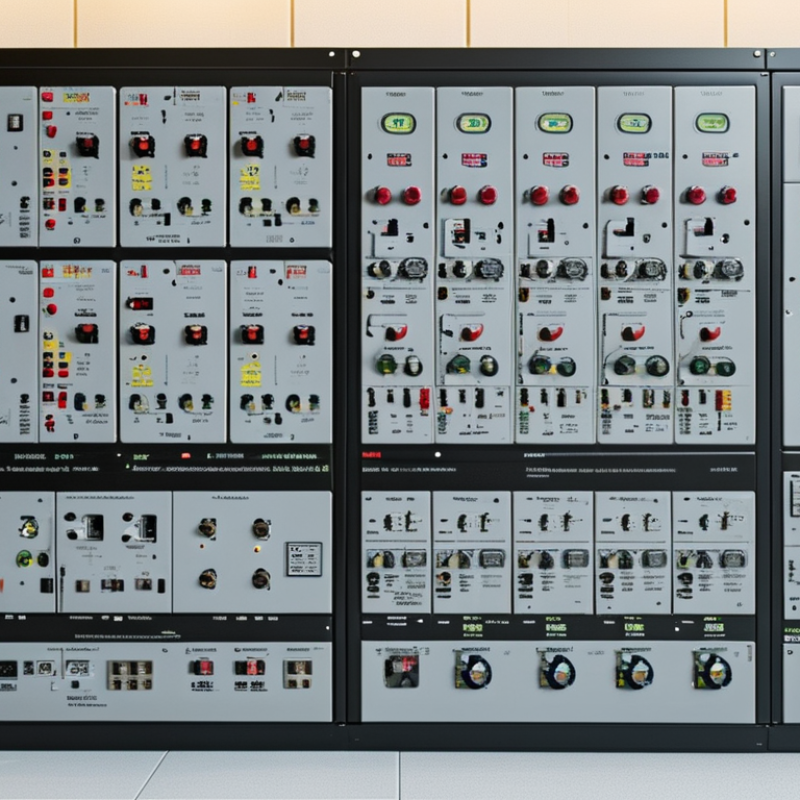
Choosing Low Voltage Switchgear for a project is a practical decision, not a catalog exercise. The right assembly must manage expected loads, fault levels, operating conditions, and future expansion. A factory, office tower, or water facility may need completely different protection and enclosure features. Small details matter. Cable entry direction, ambient temperature, maintenance access, and available floor space can affect the final selection.

A reliable evaluation begins with verified project data. Confirm the system voltage, frequency, short-circuit current, load profile, and earthing arrangement. Then compare rated current, breaking capacity, busbar construction, protection settings, and ingress protection. Check whether the equipment follows applicable requirements, such as IEC 61439, while confirming local regulations and utility rules. Manufacturer test reports, routine verification records, and clear technical drawings provide stronger evidence than impressive brochures. Ask how replacement breakers will be sourced years later.

Site experience also deserves attention. A well-designed panel should leave safe working space around terminals and removable covers. Labels must remain readable after installation. Heat calculations should reflect real conditions, including sunlight, dust, and grouped cables. A neat spreadsheet can still mislead. Project assumptions often change after procurement. Therefore, review the design with electricians, consultants, and the equipment manufacturer before approval. Low Voltage Switchgear should support dependable operation, safe maintenance, and sensible lifecycle costs. The cheapest offer may become expensive when access is poor or spare parts disappear. Careful selection is not perfect, but it reduces avoidable surprises.
How to Choose Low Voltage Switchgear for Your Project?

Define System Voltage and Fault Levels: ≤1,000 V AC or 1,500 V DC

Before choosing low voltage switchgear, confirm the system voltage at the equipment terminals. Low voltage generally means up to 1,000 V AC or 1,500 V DC. Do not rely only on the nominal supply label. Check frequency, phase arrangement, earthing method, and voltage tolerance. A 400 V three-phase system requires different clearances and insulation coordination from a 690 V system.

Then establish the available fault level at the installation point. Request data from the utility, transformer manufacturer, or a verified short-circuit study. Record the prospective short-circuit current, peak current, and fault duration. For an assembly, compare these values with its short-time withstand current, peak withstand current, and short-circuit rating. The protective device must interrupt the fault safely. Its coordination with downstream breakers also matters.

Small details change the result.

Cable length, transformer impedance, and parallel feeders can raise or reduce fault current. I have seen preliminary drawings omit future generators, creating an unrealistically low fault level. That error can affect enclosure strength and protection settings. Recheck the study after major design changes. Use equipment tested under applicable assembly standards, and keep test reports, calculations, and settings accessible for inspection. A technically acceptable selection can still fail if field wiring differs from the design. Perform a site verification before energizing, even when the paperwork appears complete.

Size Busbars for Continuous Current, Diversity, and 50–60 Hz Operation

Choosing low voltage switchgear starts with the busbar, not the enclosure. The International Energy Agency’s Electricity 2024 report expects global electricity demand to increase by more than 2,500 TWh between 2024 and 2026. That growth makes spare capacity valuable, but oversized copper also increases cost, weight, and heat storage.

Calculate the continuous design current from real operating loads. Apply diversity only when simultaneous operation is supported by measured data or a documented load schedule. Then check ambient temperature, enclosure ventilation, installation position, and conductor spacing. IEC 61439-1 and IEC 61439-2 require verified temperature-rise performance for low-voltage assemblies. A busbar that looks adequate on paper may still run hot inside a crowded cabinet. Experience matters here.

Frequency deserves attention. At 50–60 Hz, busbar losses depend mainly on RMS current, resistance, joint quality, and enclosure heat dissipation. Skin and proximity effects are usually manageable, yet they should not be ignored in high-current assemblies. Confirm the manufacturer’s verified rating at the project frequency, rather than converting a 50 Hz value casually. Include neutral loading where nonlinear loads create third-harmonic currents. Also verify short-time withstand current and peak withstand current against the available fault level, using the applicable installation rules and fault study. I would leave practical headroom, but not choose an arbitrary 25 percent margin. That habit can hide poor load data. Recheck the design when motors, drives, or future feeders change.

How to Choose Low Voltage Switchgear for Your Project? - Size Busbars for Continuous Current, Diversity, and 50–60 Hz Operation

Selection Dimension Project Data or Design Basis Illustrative Value How to Apply It to Switchgear and Busbars
System voltage Low-voltage AC distribution system 400 V, three-phase, four-wire, 50 Hz Confirm the rated operational voltage of the switchboard, insulation system, connected loads, transformers, and protection devices. Low-voltage AC equipment is commonly designed for systems up to 1,000 V AC, subject to the applicable standard and project specification.
Operating frequency Utility or generator frequency 50 Hz or 60 Hz Choose equipment rated for the actual frequency. A 50 Hz and 60 Hz system may have different interrupting, thermal, motor, transformer, and protection requirements; do not assume that frequency is interchangeable without verification.
Connected load Total installed three-phase load 720 kW at 0.90 power factor Use the connected load as the starting point, then apply demand, diversity, motor-starting, harmonic, and future-expansion requirements rather than sizing directly from the sum of nameplate ratings.
Diversity factor Expected simultaneous loading 0.80 applied to connected load Demand load = 720 kW × 0.80 = 576 kW. The diversity factor must be supported by the operating profile, load schedule, or applicable electrical design rules; it should not be used to reduce required continuous ratings where simultaneous operation is possible.
Calculated operating current Three-phase current after diversity Approximately 924 A at 400 V and 0.90 power factor I = P ÷ (√3 × V × PF)
For this example: 576,000 ÷ (1.732 × 400 × 0.90) ≈ 924 A.
Future expansion allowance Reserved capacity for planned growth 25% allowance Design current = 924 A × 1.25 ≈ 1,155 A. Select the next suitable standard assembly rating, subject to temperature-rise verification and the manufacturer’s tested configuration.
Continuous busbar rating Required current-carrying capacity The busbar assembly should have a continuous current rating at least equal to the calculated design current. A 1,250 A rating is suitable for the illustrative 1,155 A requirement only when the complete assembly, ambient conditions, enclosure, spacing, and temperature-rise test data support it.
Typical current-rating selection Common project rating steps 630 A, 800 A, 1,000 A, 1,250 A, 1,600 A, 2,000 A, 2,500 A, 3,200 A, 4,000 A, 5,000 A, 6,300 A Use the next appropriate rating above the calculated design current. These values are common selection points, not a substitute for the tested rating of the specific switchgear assembly.
Neutral busbar Neutral current and nonlinear loads Full-size neutral for significant electronic loads Data centers, LED lighting, variable-speed drives, office equipment, and other nonlinear loads can produce third-harmonic neutral current. A reduced neutral should only be used after a documented harmonic and load-current assessment.
Protective conductor PE or PEN arrangement Separate PE and neutral where required by the earthing system Size and arrange protective conductors according to the earthing system, prospective fault current, disconnection time, and applicable installation rules. Do not treat the protective conductor as an ordinary load-carrying busbar.
Short-circuit withstand Prospective fault current at the switchboard Example: 50 kA RMS for 1 second; peak withstand verified separately Specify the short-time withstand current, peak withstand current, and duration required at the installation point. The busbar supports, joints, enclosure, and protective devices must be verified as one coordinated assembly.
Interrupting capacity Fault interruption capability of circuit breakers Selected above the calculated prospective short-circuit current Verify the circuit breaker’s rated ultimate and service short-circuit breaking capacities at the actual system voltage and frequency. Do not select breakers from continuous current alone.
Ambient temperature Temperature around the switchboard 35 °C design ambient; higher values require derating review Busbar temperature rise depends on ambient temperature, enclosure ventilation, installation position, grouping, and loading pattern. Apply the assembly manufacturer’s derating data when ambient temperature or installation conditions differ from the tested reference conditions.
Altitude Installation elevation 1,000 m or below without special altitude adjustment in many designs At higher altitudes, reduced air density can affect cooling and insulation performance. Confirm current derating, dielectric clearances, and switching-device ratings for installations above the reference altitude.
Power factor and motor loads Load type and starting behavior 0.90 operating power factor; motors may have high starting current Check voltage drop, starting current, generator capability, and transient effects. A busbar sized only for steady-state kW may not be adequate for motor starting or large transformer energization.
Harmonic content Nonlinear loads and rectifier equipment Assess total harmonic distortion and triplen harmonics Harmonics can increase RMS heating in busbars, neutrals, transformers, and connections. Include harmonic currents in the thermal design where power electronics or rectifier loads are substantial.
Busbar material Conductor material and joint treatment Copper or aluminum, with compatible plated or treated joints Material choice affects conductivity, mass, expansion, joint design, corrosion resistance, and enclosure dimensions. Use joint hardware and surface treatment compatible with the selected conductor material.
Ingress protection Enclosure protection against solids and water Example: IP31 indoors; IP54 where dust or water exposure is expected Select the enclosure rating from the actual environment. Higher ingress protection can reduce natural ventilation and may require thermal derating or a verified cooling arrangement.
Applicable verification Low-voltage switchgear assembly compliance Require documented verification for temperature rise, dielectric properties, short-circuit withstand, protective circuit continuity, clearances, creepage distances, and mechanical operation for the complete assembly.
Final selection result Illustrative project outcome This example is appropriate only as a preliminary selection for the stated 924 A diversified load, 25% growth allowance, and assumed installation conditions. Final approval requires verified thermal performance, fault-current coordination, environmental review, and confirmation of the local electrical requirements.
Design note: All ratings are illustrative engineering values. Final busbar dimensions and switchgear ratings must be confirmed from the complete load schedule, installation conditions, prospective fault-current study, coordination study, and tested assembly documentation.

Verify Short-Circuit Ratings: Icw, Ipk, and Icc Under IEC 61439

How to Choose Low Voltage Switchgear for Your Project?

When selecting low voltage switchgear, short-circuit performance deserves more attention than enclosure size or appearance. Under IEC 61439, compare the assembly’s Icw, Ipk, and Icc ratings with the calculated fault level at the installation point.

Icw is the rated short-time withstand current, commonly specified for a defined period such as one second. It shows whether the assembly can withstand thermal and mechanical stress before protective devices operate. Ipk is the rated peak withstand current. It addresses the first current peak, which can create severe electromagnetic forces inside busbars and connections. Icc is the rated conditional short-circuit current, used with a specified short-circuit protective device. The rating is valid only when that device operates within the stated conditions.

Check the project voltage, frequency, fault duration, and prospective short-circuit current. Do not rely on a single number. A panel may have adequate Icw but insufficient Ipk for the available peak current. The reverse can also create confusion. Review the manufacturer’s IEC 61439 verification documents, including the tested configuration, protective device type, and cable arrangement. Small layout changes can affect performance.

Be precise here.

In field reviews, engineers sometimes copy the highest fault rating from a previous project. That habit is risky. Network impedance, transformer size, and protection settings may differ. I also recommend checking whether the specified Icc depends on a particular breaker or fuse. If that device changes during procurement, the original rating may no longer apply. A final coordination review can prevent an expensive and avoidable mismatch.

How to Choose Low Voltage Switchgear for Your Project?

Verify Short-Circuit Ratings: Icw, Ipk, and Icc Under IEC 61439

How to read the chart: Icw is the rated short-time withstand current in kA rms for a specified duration, commonly 1 second. Ipk is the rated peak withstand current in kA peak and is derived using the IEC 61439 peak factor for the applicable prospective fault-current range. Icc is the conditional short-circuit current in kA rms and is valid only when the specified short-circuit protective device is used. Confirm that each rating is equal to or higher than the prospective short-circuit current at the installation point.

Choose Enclosure Protection from IP20 to IP66 Using IEC 60529

How to Choose Low Voltage Switchgear for Your Project?

When selecting low voltage switchgear, enclosure protection is more than a catalogue number. IEC 60529 defines the Ingress Protection, or IP, rating through two digits. The first digit describes protection against solid objects and dust. The second describes resistance to water.

IP20 Protects against finger contact but offers no water protection.
IP44 Suits indoor areas with occasional splashing.
IP54 Limits dust entry and resists water spray.
IP65 Is dust-tight and handles water jets.
IP66 Withstands stronger water jets, but it is not designed for continuous immersion.

The project environment should guide your decision. A clean electrical room may need only IP20, especially when access is controlled. A workshop with dust, oil mist, and cleaning activity usually requires a higher rating. Outdoor equipment may need IP65 or IP66, depending on rainfall, hose cleaning, and enclosure orientation.

Remember that the complete assembly matters. Cable glands, door seals, ventilation openings, and maintenance work can reduce real protection. IP66 on the enclosure does not guarantee IP66 after poor installation.

Tips: Inspect the site personally when possible. Note dust, water direction, condensation, and cleaning methods. Do not choose IP66 automatically. It can increase heat retention and complicate cooling. Check thermal calculations, cable entries, and inspection access with a qualified engineer. I have seen well-rated enclosures fail because one unused entry was left open. The label was correct. The installation was not. Recheck the rating after every modification.

Confirm Form Separation, Cooling, and Service Access Before Approval

How to Choose Low Voltage Switchgear for Your Project?

Confirm Form Separation, Cooling, and Service Access Before Approval

Form separation is not a decorative specification. Under IEC 61439, Form 2 separates busbars from functional units, while Forms 3 and 4 provide greater separation between circuits and terminals. Choose the form according to maintenance risk, fault exposure, and required continuity. A higher form may improve service safety, but it also increases space, cost, and heat barriers. I would not approve a panel from a form number alone. Review internal partitions, cable terminals, and access drawings together.

Cooling deserves equal attention. The IEA’s Electricity 2024 report estimates that data centres consumed about 460 TWh globally in 2022. Their demand could exceed 1,000 TWh by 2026. Higher loads make thermal design less forgiving. Check heat-loss calculations, ventilation paths, ambient temperature, and derating values. A panel can pass a basic inspection yet develop hot spots when filters become dusty. That detail is easy to underestimate.

Service access should be tested on paper before delivery. Uptime Institute’s 2023 Global Data Center Survey reported that roughly six in ten operators experienced an outage within three years. Poor access can extend recovery time. Leave safe working clearance for breakers, cable lugs, and inspection tools. Confirm whether technicians can isolate one feeder without disturbing adjacent circuits. Door swing matters. So does lighting. One practical improvement is a full-size mock-up, although many projects skip it. That may be a mistake worth reconsidering.

Go to Top