
INDUSTRIES2023-04-26T19:33:38+00:00

How to Choose the Right FANUC Encoder?

Choosing the right Fanuc Encoder is not a simple matter of matching a part number. It is a decision about feedback accuracy, machine stability, and long-term maintenance. A spindle encoder may face vibration, heat, oil mist, and continuous high-speed rotation. A servo motor encoder may require different resolution, communication, and mounting features. Small differences matter.

Industrial automation writer and motion-control specialist John Rinaldi has stated, “Choose feedback for the machine’s real conditions, not merely for the motor.” This principle deserves attention. The correct Fanuc Encoder must match the motor model, shaft dimensions, connector design, signal type, and controller compatibility. Check the original label carefully. One missing suffix can change the encoder’s electrical interface or installation method.

Look beyond resolution. Confirm whether the application needs incremental or absolute feedback. Check supply voltage, output format, allowable temperature, protection rating, and cable length. A replacement may fit physically but still produce unstable signals. That mistake can create servo alarms, positioning errors, or unexpected downtime. It happens.

Real maintenance experience also reveals an uncomfortable truth: the cheapest encoder is rarely the cheapest solution. A low-cost unit may require repeated alignment, rewiring, or emergency replacement. However, premium pricing alone does not guarantee suitability. Verify specifications through FANUC documentation, authorized distributors, and qualified technicians. Record the old encoder’s model, machine symptoms, and installation measurements. Then compare them against the new selection. There is room for doubt, and that is useful. Careful engineers question assumptions before the machine stops.
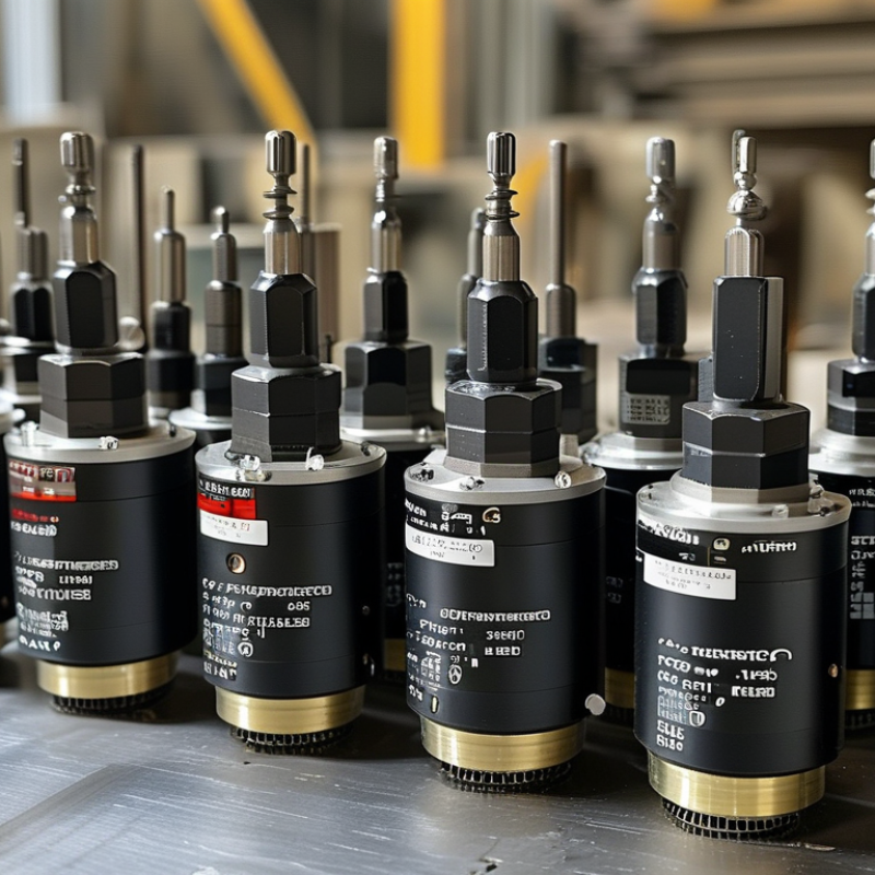
How to Choose the Right FANUC Encoder?

Identify the FANUC Encoder Type Required by Your Machine

Choosing the right encoder begins with identifying the type your machine actually requires. An industrial CNC machine may use a rotary or linear encoder. Its feedback can be incremental, absolute, or serial. These types are not interchangeable. An incremental unit may need reference return after power loss. An absolute unit usually retains position data. Check the machine drawings, control manual, and replacement label before ordering.

Record the shaft size, mounting pattern, connector shape, cable length, resolution, and supply voltage. Also confirm the feedback protocol and rotation direction. A connector may look identical while carrying different signals. That mistake can cause unstable positioning or a drive alarm. I have seen technicians measure the housing carefully but overlook the communication format. The machine then remained offline longer than expected.

Power must be isolated before inspection. Photograph the installed encoder and mark each cable connection. Compare every detail with an authorized technical document, not only an online picture. If the label is damaged, trace the cable to the drive and check the parameter settings. Do not rely on memory. Even experienced technicians can confuse two nearly identical models. A small mismatch matters. Allow room for uncertainty, and verify the part with the machine’s service records before installation.

Match Encoder Specifications With the Servo Motor and Drive

How to Choose the Right FANUC Encoder?

Match Encoder Specifications With the Servo Motor and Drive

Start with the motor datasheet. Confirm the encoder’s mounting pattern, shaft size, feedback type, and electrical interface. Fit is not enough. The encoder must also match the servo drive’s input requirements. Check whether the system uses incremental, absolute, serial, or resolver feedback. A drive designed for serial communication may not read simple pulse signals correctly.

Resolution deserves careful attention. A higher count can improve positioning, but it may exceed the drive’s processing range or create unnecessary data traffic. Verify counts per revolution, maximum speed, supply voltage, current, and cable length. Also check the feedback connector and pin arrangement. One reversed signal pair can cause unstable motion or an incorrect rotation direction. Small details matter.

Mechanical alignment is equally important. Measure the shaft diameter, coupling style, body clearance, and allowable axial movement before ordering. Dust, vibration, and heat near the motor can shorten encoder life, so select suitable protection and temperature ratings. A practical test is to compare the motor, encoder, and drive manuals side by side. Do not rely on appearance. I have seen similar housings conceal different signal standards. That assumption can delay commissioning. After installation, confirm the drive parameters, rotation feedback, alarm response, and position stability at low speed. Recheck everything.

How to Choose the Right Encoder? Match Encoder Specifications With the Servo Motor and Drive

The chart shows the feedback pulse frequency generated at 3,000 motor RPM for common incremental encoder resolutions. Quadrature decoding produces four counts per pulse, so the required drive input frequency increases with encoder resolution.

Select an encoder whose output type, voltage level, resolution, maximum speed, and feedback interface are supported by both the servo motor and the drive. At 3,000 RPM, the required frequency is calculated as: RPM × counts per revolution ÷ 60. Always compare this requirement with the drive's maximum feedback-input frequency.

Verify Resolution, Feedback Signals, and Communication Protocol

Choosing the right encoder starts with resolution, but resolution alone does not guarantee accuracy. Check counts per revolution, interpolation, maximum output frequency, and mechanical repeatability. A 20-bit absolute encoder may provide fine position data, yet poor mounting or shaft vibration can still create errors. The International Federation of Robotics reported 541,302 industrial robots were installed worldwide in 2023, increasing pressure on motion systems to deliver stable, repeatable feedback. Small errors matter.

Feedback signals must match the controller and drive. Incremental A/B/Z signals suit many retrofit systems, while absolute serial feedback can reduce homing time and preserve position after power loss. Verify differential signaling, voltage levels, signal direction, index behavior, and alarm outputs. In commissioning work, I have seen wiring noise imitate encoder failure. Shielding and grounding deserve more attention than they usually receive.

Communication protocol compatibility is equally important. Confirm connector pinout, data frame format, update rate, timing limits, and diagnostic functions. A protocol may transfer position correctly but still fail when the controller expects a different cycle time or error response. IEC 61800-5-2 emphasizes defined safety-related control behavior, but it does not replace application testing. I would test the encoder under heat, vibration, cable flexing, and rapid reversals. Specifications look convincing on paper. Real machines are less polite.

Check Mechanical Fit, Connector Design, and Environmental Ratings

How to Choose the Right Encoder?

Choosing an encoder starts with mechanical fit, not price or appearance. Check the shaft diameter, mounting pattern, body length, and allowable insertion depth. A shaft can look correct yet fail under side loading. Small errors matter.

Match the encoder’s rotational direction and resolution to the motion system. Confirm whether the coupling needs a keyway, clamp, or flexible connection. I have seen installations fail because the encoder body touched a nearby bracket during rotation. Leave practical clearance. Do not guess. Use the equipment drawing and the encoder datasheet together.

Tips: Inspect the connector before ordering. Compare pin count, key position, locking method, and cable exit direction. A similar connector may still have a different signal arrangement. Verify supply voltage, output type, and cable shielding with a qualified technician.

Environmental ratings also deserve careful attention. Check operating temperature, humidity, vibration, dust protection, and oil resistance. A sealed housing helps, but it does not solve every installation problem. Condensation can enter through an exposed connector or poorly routed cable. Use the specified sealing accessories, and avoid sharp bends near the connector. I sometimes see teams focus on the enclosure rating while ignoring vibration at the mounting point. That is an easy mistake to repeat. When conditions are uncertain, record actual temperatures and inspect the installation after several operating cycles.

Confirm Compatibility, Part Numbers, and Replacement Requirements

Choosing the right industrial encoder starts with compatibility, not appearance. Confirm the motor series, feedback type, resolution, voltage, shaft design, connector, and mounting pattern. A similar housing can hide a different communication protocol. One detail is easy to miss.

In field service, I have seen replacements fail because technicians checked only the visible part number. Compare every character, suffix, revision code, and connector position with the installed unit. Record the machine model and encoder label before removal. Use technical drawings and verified cross-reference data, not marketplace photographs. A close match can still produce alarms, unstable positioning, or incorrect speed feedback.

Replacement requirements also deserve careful attention. Check whether the new encoder needs a dedicated cable, coupling, adapter, or updated control parameters. Inspect the shaft for scratches and measure mounting alignment before installation. Back up machine parameters first. Keep the original wiring order documented. After fitting the encoder, verify direction, reference position, signal quality, and repeatability at low speed. Some systems require a homing cycle or calibration routine. Do not assume automatic setup will work. It may not. Environmental ratings matter too, especially where oil mist, vibration, heat, or metal dust is present. If the exact part number is unavailable, pause and obtain written technical confirmation before substituting it. That small delay is safer than correcting a damaged drive or lost position data.

How to Choose the Right FANUC Encoder? - Confirm Compatibility, Part Numbers, and Replacement Requirements

Compatibility Dimension What to Confirm Common Specifications Why It Matters Replacement Requirement
Encoder Type Identify whether the feedback device is incremental or absolute. Incremental; absolute serial; battery-backed absolute. The controller feedback circuit must support the same signal and data method. Do not substitute an incremental encoder for an absolute encoder without controller-level approval.
Mechanical Interface Check shaft diameter, shaft length, mounting pattern, pilot diameter, and housing clearance. Solid shaft or hollow shaft; flange or servo-motor mounting; keyed or keyless shaft. Small dimensional differences can cause misalignment, vibration, or installation failure. Match the original mounting geometry and shaft coupling arrangement.
Electrical Supply Verify operating voltage, current consumption, and permissible voltage tolerance. Typical industrial encoder supplies include 5 VDC or 10–30 VDC, depending on the interface. Incorrect voltage may produce unstable feedback or permanent electronic damage. Use the voltage shown on the original label or equipment documentation.
Output Interface Confirm differential or single-ended outputs and the supported communication protocol. A/B/Z incremental signals; differential line-driver outputs; serial absolute feedback. The receiving controller must recognize the encoder’s electrical and communication format. A similar connector does not guarantee electrical compatibility.
Resolution Record pulses per revolution for incremental units or bits per revolution for absolute units. Incremental resolution is commonly specified in PPR; absolute resolution is commonly specified in bits. Resolution affects positioning accuracy, control tuning, and feedback scaling. Use the same resolution unless the controller parameters and machine design permit a verified change.
Signal Direction and Phase Check A/B phase relationship, index position, counting direction, and commutation signals where applicable. Quadrature A/B channels; once-per-revolution index; optional motor commutation feedback. Incorrect phasing can cause reversed motion, position errors, or drive alarms. Compare the replacement waveform and rotation direction with the original device.
Connector and Pinout Confirm connector style, pin count, keying, wire colors, shielding, and terminal assignments. Circular industrial connectors, sealed connectors, or dedicated motor-feedback plugs. Pinout differences can short the supply or place signals on incorrect input channels. Use a verified pin-to-pin wiring diagram; never rely on connector appearance alone.
Cable Requirements Check cable length, conductor count, impedance, shielding, flex rating, and grounding method. Shielded twisted-pair cable is commonly used for differential encoder signals. Poor shielding or excessive cable length can increase noise and feedback faults. Reuse the original cable only after checking insulation, continuity, shielding, and connector condition.
Environmental Rating Review operating temperature, humidity, ingress protection, shock, vibration, and oil resistance. Industrial units often support approximately 0–70°C, while extended-temperature models vary by design. The encoder must withstand the actual motor and cabinet environment. Select an equal or higher environmental rating for the application.
Maximum Speed Compare rated rotational speed with the motor’s maximum operating speed. Rated speed is specified in revolutions per minute and depends on bearing, code disk, and mechanical design. Overspeed can reduce accuracy, damage bearings, or shorten service life. Choose a replacement with a speed rating at least equal to the machine requirement.
Part Number Identification Record every character, suffix, revision code, connector code, and date or batch marking. Part numbers may encode resolution, shaft design, communication type, cable option, or revision. A single suffix can represent a different electrical or mechanical configuration. Order by the complete verified part number rather than a shortened housing label.
Controller and Motor Pairing Confirm the encoder is approved for the specific motor, drive, amplifier, and control software configuration. Feedback parameters may include encoder type, resolution, polarity, offset, and electronic gearing. A mechanically compatible encoder may still fail initialization or servo tuning. Verify required parameter settings before powering the machine after replacement.
Battery and Position Retention Determine whether the absolute feedback system uses an external or internal backup battery. Battery-backed systems may require position retention during power loss. Battery failure or replacement without procedure may cause reference-position loss. Follow the machine’s battery replacement and re-referencing procedure.
Installation and Calibration Check alignment marks, coupling torque, mounting torque, zero position, and feedback calibration steps. Calibration may involve a servo initialization, reference return, or position offset procedure. Incorrect installation can create repeatability errors even when the part is electrically correct. Record the original orientation and complete the specified calibration before production use.
Final Verification Compare the label, datasheet, wiring diagram, mechanical drawing, and controller alarm history. Use a compatibility checklist covering mechanical, electrical, environmental, and software requirements. Cross-checking prevents errors caused by visually similar encoder models. Approve the replacement only when all critical specifications match or are formally validated.
Selection Note: Always verify the complete encoder identification and machine documentation before installation. Connector shape or housing appearance alone is not sufficient evidence of compatibility.
Go to Top