
INDUSTRIES2023-04-26T19:33:38+00:00

How to Choose the Right Stamped Contact Spring?

Choosing the right Stamped Contact Spring is not simply a matter of matching dimensions. It requires a clear understanding of electrical, mechanical, and environmental demands. A spring may look suitable on a drawing, yet fail after repeated compression or surface contamination. That assumption can be costly.

Start with the real operating conditions. Define the required contact force, working deflection, current level, and available space. Consider how often the spring will cycle. A battery connector used daily needs different fatigue performance from a sensor assembled once. Material selection also matters. Stainless steel offers corrosion resistance, while copper alloys often provide better conductivity. Plating can further improve contact stability, but only when its thickness suits the application. Small details matter here.

Manufacturing experience should guide the final decision. Stamping tolerances, burr control, springback, and forming direction can affect both fit and reliability. Ask suppliers for material certificates, dimensional reports, and performance data. Prototype testing should measure force loss, contact resistance, temperature rise, and wear under realistic conditions. A laboratory result is useful, but real assembly conditions may expose weaknesses. Do not ignore that possibility.

The best choice balances performance, cost, manufacturability, and service life. A cheaper spring is not always economical if replacement requires opening the entire product. Engineers should compare several designs rather than trusting one familiar profile. Review the supplier’s quality procedures and testing methods carefully. Even experienced teams can overlook installation variation. Careful verification turns a promising Stamped Contact Spring into a dependable component.
How to Choose the Right Stamped Contact Spring?

Understanding the Structure and Function of Stamped Contact Springs

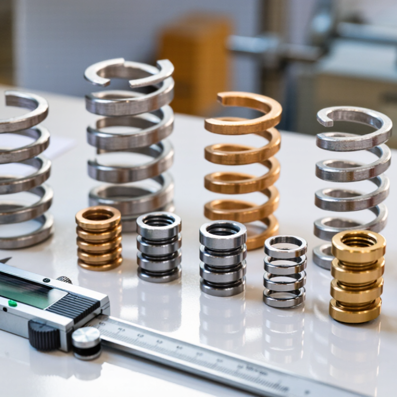
Choosing the right stamped contact spring begins with understanding its structure. A thin metal strip is stamped into a controlled shape. Its main features include contact beams, bends, mounting tabs, and retention points. Each feature has a specific job.

The contact beam creates the normal force against a mating surface. Its length, width, thickness, and bend angle determine spring travel and electrical stability. A longer beam usually provides greater movement, but it may lose force more quickly. Short beams can resist vibration, though they often require tighter assembly tolerances. Small embossments or ribs may improve stiffness without adding much material.

The current path also matters. Contact points should remain clean and stable during repeated movement. Material selection affects conductivity, fatigue resistance, and heat behavior. Surface treatment can reduce oxidation, but it cannot fix poor geometry. In practical testing, I check contact force at several deflection points, not just one target position. I also inspect permanent deformation after cycling.

A spring may appear perfect in a drawing. Reality is less polite. Stamping burrs, uneven plating, and slight alignment errors can change performance. Engineers should review tooling capability and measured samples together. I have found that early prototypes sometimes reveal weaknesses hidden by computer models. Reliable selection depends on repeatable data, realistic tolerances, and the actual working environment.

Defining Electrical, Mechanical, and Environmental Requirements

How to Choose the Right Stamped Contact Spring?

Defining Electrical, Mechanical, and Environmental Requirements

A stamped contact spring should start with electrical data, not its shape. Record rated current, working voltage, allowable resistance, and temperature rise. Copper alloys conduct well, but excessive current density can soften the spring. IEC 60512 test methods measure contact resistance under controlled conditions. Use them to compare samples, not only drawings. The International Energy Agency’s Global EV Outlook 2024 reports nearly 14 million electric-car sales in 2023. More compact power systems mean tighter thermal margins inside connectors.

Mechanical requirements need equal attention. Specify normal force, free height, working deflection, and expected mating cycles. A spring that feels strong during assembly may lose force after repeated compression. Check stress against the material’s fatigue limits. Measure force at the real operating position. The first calculation is often wrong. I have seen designs pass static checks but fail after vibration testing because the support area was too short.

Environmental exposure can change the selection completely. Define temperature range, humidity, salt mist, dust, chemicals, and vibration before choosing plating or geometry. ISO 16750-4:2023 provides environmental test guidance for road-vehicle electrical equipment. Its vibration and climatic loads help create realistic validation plans. Test at temperature extremes, not only at room temperature. Also inspect fretting marks under magnification. A small oxide film or a slightly misaligned spring can increase resistance unexpectedly. That detail is easy to miss.

Selecting Materials, Dimensions, and Contact Configurations

Choosing a stamped contact spring starts with material selection, not geometry. Copper alloys offer excellent conductivity, while stainless steel provides stronger spring recovery. The U.S. Geological Survey’s Mineral Commodity Summaries 2025 reported approximately 22 million metric tons of global copper mine production in 2024. That scale supports copper availability, but it does not guarantee stable pricing or suitable performance. Use copper alloys for low-resistance paths, then verify strength after stamping and heat treatment.

Small changes matter. Define the required current, working temperature, mating cycles, and acceptable contact resistance. A 0.10-millimeter thickness can behave very differently from 0.15 millimeters under the same load. Measure force at the real operating deflection, not only at the drawing’s nominal position. ASTM B193 supports resistivity testing, while IEC 60512 provides recognized methods for contact resistance and mechanical testing. These references improve reliability, but fixture design still affects results. I have seen testing become misleading when the spring was clamped too tightly.

Contact configuration should match movement. A wiping beam can break light surface films, while a stable button contact suits controlled, repeated compression. Specify the contact radius, normal force, deflection limit, and plating thickness. The International Energy Agency’s Global Critical Minerals Outlook 2024 projects rising copper demand through 2035, so material substitutions may become more common. Nickel-based or stainless options may reduce supply risk, but they can increase resistance. Do not guess. Prototype two thicknesses, inspect wear marks, and repeat testing after humidity exposure. The first design is often acceptable, not optimal.

How to Choose the Right Stamped Contact Spring?

Representative material-property comparison for selecting stamped contact springs. Conductivity is shown as a percentage of the International Annealed Copper Standard (IACS), while tensile strength is shown in MPa. Actual values vary with alloy temper, strip thickness, and forming process.

Material

Choose copper alloys when low electrical resistance is essential. Beryllium copper offers high strength, while phosphor bronze provides a balanced combination of spring performance and conductivity.

Dimensions

Strip thickness, free length, width, bend radius, and working deflection determine contact force and fatigue life. Use the smallest deflection that achieves reliable contact pressure.

Contact Configuration

Single-beam contacts are compact, while dual-beam and redundant contacts improve electrical continuity and tolerance to misalignment. Select the configuration according to current, travel, and available space.

Evaluating Manufacturing Quality, Performance, and Service Life

How to Choose the Right Stamped Contact Spring?

Manufacturing quality determines whether a stamped contact spring performs consistently. Inspect the strip material, burr height, plating thickness, and forming accuracy. A polished surface is not proof of reliability. IPC’s 2024 Technology Roadmap identifies miniaturization and higher current density as continuing electronics industry pressures. These trends leave less room for dimensional variation.

A polished surface is not proof of reliability.

Ask for measurable evidence, not attractive samples. A qualified supplier should provide dimensional inspection records, material certificates, plating analysis, and force-deflection curves. The Spring Manufacturers Institute’s Handbook of Spring Design links fatigue performance to stress level, surface condition, and residual stress. In practice, a small forming mark can become a crack after repeated deflection.

I have seen teams overlook this detail. It was not a clever decision.

Performance testing should reflect the real assembly.

IEC 60512 durability methods can evaluate mechanical operation, contact resistance, and environmental exposure, but the cycle count must match the application. Test at temperature extremes, vibration levels, and expected compression distances. ASTM B117 salt-spray results can reveal corrosion resistance, yet they do not predict complete field life. That limitation matters.

Record initial and final contact force, resistance drift, and permanent set. A spring that passes one test may still fail after storage, installation, or thermal cycling. Service life should be estimated from application-specific data, then reviewed after pilot production.

Comparing Suppliers and Confirming the Final Spring Selection

How to Choose the Right Stamped Contact Spring?

Comparing Suppliers and Confirming the Final Spring Selection

When choosing a stamped contact spring, supplier comparison often determines production success. A drawing alone is not enough. Ask each supplier for load-deflection data, contact resistance results, material certificates, and dimensional inspection records. Compare these documents under identical test conditions. Check whether the supplier understands your required force, working stroke, temperature range, and installation space.

Experience matters during sample evaluation. Measure the spring with the intended mating surface, not only with laboratory fixtures. Inspect burrs, cracks, plating coverage, and contact alignment under magnification. Request samples from different production batches when possible. One attractive prototype can hide process variation. I once focused too heavily on initial force and overlooked unstable electrical resistance after repeated cycling. That mistake changed the final selection.

Tips: Create a supplier scorecard with quality, tooling control, delivery reliability, technical support, and total cost. Ask how they control forming wear and material thickness. Confirm packaging before approval; bent contacts can arrive inside a perfect-looking carton. Run a pilot batch, then repeat key tests after storage and temperature cycling. Keep every approval sample, measurement, and revision in one controlled record. Do not approve based on price alone. A slightly higher unit cost may prevent costly assembly interruptions. Be willing to revise the specification when test evidence challenges the original design.

How to Choose the Right Stamped Contact Spring? - Comparing Suppliers and Confirming the Final Spring Selection

Selection Criteria Option A Option B Option C Recommended Target
Base material AISI 301 stainless steel, half hard AISI 301 stainless steel, full hard Phosphor bronze, spring temper AISI 301 stainless steel, selected temper
Typical application fit General signal-contact applications High-cycle, compact contact assemblies Low-voltage contacts requiring high conductivity Based on current, travel, environment, and cycle life
Strip thickness 0.25 mm 0.20 mm 0.30 mm 0.20–0.30 mm, confirmed by force and space limits
Nominal contact force 0.55 N at 0.35 mm deflection 0.70 N at 0.30 mm deflection 0.50 N at 0.35 mm deflection 0.50–0.70 N, subject to electrical resistance testing
Working deflection 0.35 mm 0.30 mm 0.35 mm Keep below the specified elastic limit
Dimensional tolerance ±0.05 mm on critical features ±0.03 mm on critical features ±0.05 mm on critical features Set tolerances according to mating-part capability
Electrical contact resistance ≤30 mΩ after assembly ≤25 mΩ after assembly ≤15 mΩ after assembly Limit confirmed by the finished contact system
Surface finish Deburred and cleaned Deburred, cleaned, and passivated Nickel underplate with selective gold contact area Finish selected for oxidation, wear, and mating compatibility
Estimated cycle capability Approximately 100,000 cycles Approximately 500,000 cycles Approximately 250,000 cycles Verify through application-specific life testing
Prototype lead time 3–4 weeks 4–5 weeks 4–6 weeks Short enough to support design verification
Production lead time 5–7 weeks after approval 6–8 weeks after approval 7–9 weeks after approval Aligned with the product launch schedule
Tooling and setup cost Low Medium Medium to high Evaluate against annual volume and expected tool life
Quality documentation Dimensional report and material certificate Dimensional report, material certificate, and force chart Material certificate, plating report, and resistance data Require traceability for material, plating, force, and inspection results
Best overall use case Cost-sensitive, moderate-duty applications High-cycle applications with limited installation space Applications prioritizing low resistance and conductivity Choose only after prototype, force, resistance, and life validation
Final selection status Reserve option Preferred option for high-cycle designs Preferred option for low-resistance designs Confirm with final assembly testing before release

All values are representative engineering comparison data. Final spring selection should be confirmed through prototype testing under the actual load, temperature, mating geometry, electrical current, corrosion exposure, and cycle requirements.

Go to Top